
National Service Hotline


National Service Hotline

Cavitation Erosion Resistance of Silicified Graphite by Liquid Silicon
Penetration Technique
Shuyun Jiang1
Professor
School of Mechanical Engineering,Southeast University,2 Southeast Road, Jiangning District,Nanjing 211189, China
e-mail: jiangshy@seu.edu.cn
This technical brief studied the cavitation erosion behavior of the silicified graphite. The phase constituents, surface microstructure,and chemical compositions of silicified graphite were examined by using X-ray diffraction (XRD), scanning electron microscopy(SEM), and energy dispersive spectroscopy (EDS), respectively.Cavitation experiments were carried out by using an ultrasonic vibration test system. The experimental results show that the silicified graphite exhibits an excellent cavitation erosion resistance;this can be attributed to the fact that the silicified graphite has thecharacteristics of both the silicon carbide and the graphite. TheSEM morphology studies of the erosion surfaces indicated that the inherent brittleness of SiC ceramic material results in the formation of erosion pits on the surface of silicified graphite.
[DOI: 10.1115/1.4035869]
Keywords: silicified graphite, cavitation erosion, erosive wear
1 Introduction
Cavitation phenomenon often occurs in the component under aqueous medium, which usually cause severe damage of its surface and shorten its life time [1–3]. Therefore, it is needed to design proper materials with cavitation erosion resistance in aqueous environment.
The graphite material is regarded as a promising material for the aqueous environment due to its attractive properties including good self-lubricating property, temperature resistance, and corrosion resistance [4]. Recently, many studies have focused on the graphite material, including the preparation technology of selflubricating carbon graphite materials for different application environments and their tribological properties such as friction and wear characteristics [5–16]. Silicified graphite is the most representative of the graphite composites. Silicified graphite, embodied the complementarity of carbon graphite material and silicon carbide,is not only good in self-lubrication behavior, thermal conductivity,thermal shock resistance, and high temperature strength, but also excellent in hardness, oxidation resistance,corrosion resistance, etc.
The tribological property of silicified graphite under waterlubricated
condition was investigated on the test rig, and the result showed that the silicified graphite layer has high wear resistance[17], and the SiC layer improves the performance of silicified graphite. The silicified graphite exhibits an excellent antiwear behavior, however, it is still worthy of studying for the cavitation erosion resistance of this material in aqueous environment. To the best of our knowledge, there is no literature concerned with the cavitation erosion resistance of silicified graphite.
In this technical brief, the cavitation erosion behavior of silicified graphite was studied using an ultrasonic vibration test system.

Fig. 1 (a) The ultrasound vibration system—photo, (b) the ultrasound vibration system—schematic diagram of system,and (c) the ultrasound vibration system—specimen
1Corresponding author.
Contributed by the Tribology Division of ASME for publication in the JOURNAL
OF TRIBOLOGY. Manuscript received September 30, 2016; final manuscript received
January 18, 2017; published online June 5, 2017. Assoc. Editor: Dae-Eun Kim.
Journal of Tribology
Copyright VC 2017 by ASME NOVEMBER 2017, Vol. 139 / 064501-1
Downloaded rom: http://asmedigitalcollection.asme.org/ on 12/04/2017 Terms of Use:
The eroded surfaces were examined by a scanning electron microscope (SEM) to study the damage mechanism of silicified graphite.In addition, the same experiments of cavitation erosion were also performed on the carbon graphite and impregnated graphite,so as to illustrate the effectiveness of the cavitation erosion resistance of the silicified graphite.
2 Cavitation Erosion Experiment
2.1 Test Apparatus. Figure 1 shows the ultrasonic vibration test system for investigating the cavitation erosion of silicified graphite. Experiments were carried out using an Ultrasonics JY92-IID ultrasound generator, operating at a frequency of 20 kHz and peak-to-peak amplitude of 12 lm. The sample was mounted on the specimen holder which was screwed in the horn.The collapse of cavitation bubbles around the horn tip causes the
cavitation erosion damage. The test liquids are tap water, saline water, and sand water. In addition, fresh liquid was used to replace the exhausted one every half an hour to ensure that the test liquid temperature in the beaker was kept constant of 20±℃
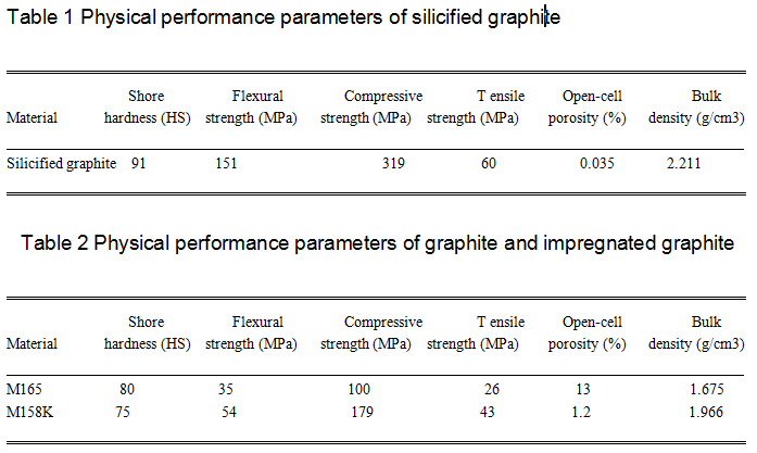
2.2 Test Samples. The dimension of the specimen was 10mm_7mm_5 mm. In this study, silicified graphite was prepared by liquid silicon penetration technique, and the impregnated thickness of the film was 0.5 mm. Silicified graphite is a multiphase
composite material composed of silicon carbide, graphite,and free silicon. Although this study focuses on the cavitation erosion resistance of silicified graphite, for comparison, the same classification of material: carbon graphite (M165) and furan resin impregnated graphite (M158K), were also tested in the cavitation experiments. Tables 1 and 2 list the physical parameters of silicified graphite, carbon graphite, and furan resin-impregnated
graphite.
Figure 2 presents the energy dispersive spectroscopy (EDS) analysis of silicified graphite; the elementary composition in weight percent (%) is: C, 13.7, O, 2.57, Si, 83.73. Figure 3 shows a X-ray diffraction (XRD) pattern of silicified graphite by using a
Smartlab (3) X-ray diffractometer (40 kv and 30 mA, Cu Ka radiation) with a step size 0.02 deg in the range of 15–100 deg, and SiC phase and C phase can be seen from XRD pattern of silicified graphite through a series of broad peak.
2.3 Experiment Procedures. Cavitation erosion tests were performed using ultrasonic vibration test system with a total test time of 14 h. for each sample, and the sample was weighed every 2 h. Subsequently, the specimens were cleaned by an ultrasonic
cleaner (KQ118) with acetone and dried in drying basin, and weighed with a 10060.01 mg sensitivity balance before and after each cavitation test. Figure 4 shows the optical photographs of carbon graphite, impregnated graphite, and silicified graphite after
cavitation tests. Figure 5 shows the optical photographs of silicified graphite after cavitation tests in the tap water, a 3.5% (by weight) solution of NaCl (reagent grade), and sand water with sediment concentration of 3 kg/m3.

Fig. 2 (a) EDS analysis of silicified graphite—The selected area for EDS analysis and (b) EDS analysis of silicified graphite—analysis result

Fig. 3 XRD pattern of the silicified graphite
064501-2 / Vol. 139, NOVEMBER 2017 Transactions of the ASME
Downloaded From: http://asmedigitalcollection.asme.org/ on 12/04/2017 Terms of Use: http://www.asme.org/about-asme/terms-of-use

Fig. 4 (a) Photo after 14 h. of cavitation test in the tap water—M165, (b) photo after 14 h. of cavitation test in the tap water—M158K, and (c) photo after 14 h. of cavitation test in the tap water—silicified graphite

Fig. 5 (a) Silicified graphite after 14 h. of cavitation test in different test liquids—before test, (b) silicified graphite after 14 h. of cavitation test in different test liquids—tap water, (c) silicified graphite after 14 h. of cavitation test in different test liquids—3.5% saline water, and (d) silicified graphite after 14 h. of cavitation test in different test liquids—sand water of 3 kg/m3
3 Experiment Results and Discussion
3.1 Cumulative Mass Loss. Figure 6 presents the cumulative mass loss curves of the carbon graphite, impregnated graphite, and silicified graphite with the test time, and the weight loss of the specimen increases with the duration time. After a 14 h. cavitation
erosion experiment, the cumulative mass loss of the silicified graphite, impregnated graphite (M158K), and carbon graphite (M165) are 3.56 mg, 8.9 mg, and 14.24 mg, respectively.
Figure 7 presents the weight loss of the silicified graphite samples in the tap water, 3.5% saline water, and 3 kg/m3 sand water as a function of experiment time. The results show that the order of mass loss from the largest to lowest was the sand water, the saline water, and the tap water. In detail, after a 14 h. test, the mass loss of the silicified graphite, the saline water, and the saline water are 3.56 mg, 8.68 mg, and 12.71 mg, respectively.
3.2 Scanning Electron Microscope Morphologies of Erosion Surface. Figure 8 shows the SEM images of carbon graphite and impregnated graphite specimens after 14 h. of cavitation erosion experiments in the tap water. As shown in Fig. 8(a), the cavitation
erosion is severe for the carbon graphite specimen, and large erosion pit can be observable. Because of the high open-cell porosity, the collapse of cavitation bubbles has a significant effect on the carbon graphite surface. Cavitation bubbles appear to attack repeatedly carbon graphite surface, leading to the formation of erosion pit. With the duration of the test, pits are aggregated and deep craters are coalesced duo to the porosity and brittleness of carbon graphite material. Figure 8(b) illustrates that the smaller erosion pit is also observed on the surface of the impregnated graphite. Owing to the lower open-cell porosity, the damage degree of impregnated graphite is not as severe as the carbon
graphite material.
Figure 9 indicates the SEM images of silicified graphite specimens in the tap water, 3.5% saline water, and 3 kg/m3 sand water before and after 14 h. of cavitation erosion experiments. As shown in Fig. 9(a), there are a lot of bright silicon carbide ceramic particles and small pores in the specimen. It is evident from Fig. 9(b) that the erosion pit is observable after cavitation erosion experiment.Comparing with the impregnated graphite (M158K) and the carbon graphite (M165), the silicified graphite has a better cavitation
erosion resistance, while some small erosion pits can be seen on the specimen surface. Silicified graphite is a multiphase composite material by depositing a layer of silicon carbide on the graphite, which has the characteristics of both the silicon carbide
and the graphite. Comparing with the impregnated graphite (M158K), and carbon graphite (M165), silicified graphite has a higher hardness, a more stable chemical property due to covalent bond of SiC, leading to a more obvious advantage in corrosion resistance and thermal shock-resistance. As shown in Fig. 9(c),the erosion pit under saline water is bigger than that under the tap water. Besides the mechanical impact, the specimen surface also
suffers from corrosion additively, so that the silicified graphite is eroded by both mechanical impact and corrosion effect. It can be seen from Fig. 9(d) that the surface damage of silicified graphite in the sand water is more serious in comparison with these in the tap water and saline water. Similarly, cavitation bubbles will collapse and directly perish the surface of silicified graphite by shock wave emission and microjet. On the other hand, shock wave emission will act on the sand particle to increase its impact velocity,
resulting in an increase in erosion of the specimen. The combined action of cavitation erosion and impact erosion aggravates the surface damage. The surface of silicified graphite is eroded by cavitation bubbles,and the collapse of cavitation bubble will cause the formation of cavitation erosion pits due to inherent brittleness. The generated pits and pores on the surface can lead to the stress concentration and the formation of crack initiation, and more material will be peeled off from the sample surface with the test time. The cavitation erosion mechanism of the silicified graphite is shown in Fig. 10.

Fig. 6 The mass loss curve of carbon, impregnated, and silicified graphite in the tap water

Fig. 7 The mass loss curve of silicified graphite in different test liquids

Fig. 8 (a) The SEM images of carbon graphite and impregnated graphite after 14 h. test in the tap water—carbon graphite and (b) the SEM images of carbon graphite and impregnated graphite after 14 h. test in the tap water—impregnated graphite
Fig. 9 (a) The SEM images of silicified graphite after 14 h. test in different test liquids—before test, (b) the SEM images of silicified graphite after 14 h. test in different test liquids—tap water, (c) the SEM images of silicified graphite after 14 h. test in different test liquids—3.5% saline water, and (d) the SEM images of silicified graphite after 14 h. test in different test liquids—sand water of 3 kg/m3

Fig. 10 The pit by brittle fracture of the silicified graphite
4 Conclusions
In this technical brief, the cavitation experiment is conducted for the silicified graphite prepared by liquid silicon penetration technique. The results show, the silicified graphite exhibited higher cavitation erosion resistance compared with the carbon graphite (M165), furan resin impregnated graphite (M158K),which can be attributed to its characteristics of both the silicon carbide and the graphite. The formation of cavitation erosion pits and pores of silicified graphite are mainly caused by the inherent brittleness of SiC ceramic material.
Acknowledgment
The authors acknowledge the financial support of the National Natural Science Foundation of China under Grant Nos. 51635004 and 11472078, and the Jiangsu University-Industry Collaboration Project under Grant No. BY2015070-26.
Silicified graphite materials manufacturer:Qingdao Huajie Silicon Carton Tech Co.,Ltd.
Contact:Sun Shaojie
Phone: 0532-87412018 87412028
Mobile phone:13884969888
Fax:0532-87412038
E-mail: 13884969888@163.com
References
[1] Jiang, S., Ding, H., and Xu, J., 2017, “Cavitation Erosion Resistance of Sputter
Deposited Cr3Si Film on Stainless Steel,” ASME J. Tribol., 139(1), p. 014501.
[2] Abouel-Kasem, A., and Ahmed, S. M., 2012, “Bubble Structures Between Two
Walls in Ultrasonic Cavitation Erosion,” ASME J. Tribol., 134(2), p. 021702.
[3] Abouel-Kasem, A., and Ahmed, S. M., 2008, “Cavitation Erosion Mechanism
Based on Analysis of Erosion Particles,” ASME J. Tribol., 130(3), p. 031601.
[4] Jia, Q., Yuan, X., Zhang, G., Dong, G., and Zhao, W., 2014, “Dry Friction and
Wear Characteristics of Impregnated Graphite in a Corrosive Environment,”
Chin. J. Mech. Eng., 27(5), pp. 965–971.
[5] Goyal, R. K., and Yadav, M., 2014, “The Wear and Friction Behavior of Novel
Polytetrafluoroethylene/Expanded Graphite Nanocomposites for Tribology
Application,” ASME J. Tribol., 136(2), p. 021601.
[6] El Mansori, M., Schmitt, M., and Paulmier, D., 1999, “Third Body Effects on
Graphite/XC48 Steel Magnetized Sliding Contact,” ASME J. Tribol., 121(2),
pp. 403–407.
[7] Liu, Y. B., Lim, S. C., Ray, S., and Rohatgi, P. K., 1992, “Friction and Wear of
Aluminium-Graphite Composites: the Smearing Process of Graphite During
Sliding,” Wear, 159(2), pp. 201–205.
[8] Rajkumar, K., and Aravindan, S., 2009, “Microwave Sintering of Copper–Graphite
Composites,” J. Mater. Process. Technol., 209(15), pp. 5601–5605.
[9] Rajkumar, K., Kundu, K., Aravindan, S., and Kulkarni, M. S., 2011,
“Accelerated Wear Testing for Evaluating the Life Characteristics of
Copper–Graphite Tribological Composite,” Mater. Des., 32(5), pp. 3029–3035.
[10] Ma, W., and Lu, J., 2011, “Effect of Sliding Speed on Surface Modification and
Tribological Behavior of Copper–Graphite Composite,” Tribol. Lett., 41(2),
pp. 363–370.
[11] Wang, J., Jia, Q., Yuan, X., and Wang, S., 2012, “Experimental Study on Friction
and Wear Behaviour of Amorphous Carbon Coatings for Mechanical Seals
in Cryogenic Environment,” Appl. Surf. Sci., 258(24), pp. 9531–9535.
[12] Guan, X., and Wang, L., 2012, “The Tribological Performances of Multilayer
Graphite-Like Carbon (GLC) Coatings Sliding Against Polymers for Mechanical
Seals in Water Environments,” Tribol. Lett., 47(1), pp. 67–78.
[13] Gulevskii, V. A., Antipov, V. I., Kolmakov, A. G., Vinogradov, L. V., Lazarev,
E. M., Mukhina, Y. E., and Gordeev, A. S., 2012, “Designing of Copper-Based
Alloys for the Impregnation of Carbon-Graphite Materials,” Russ. Metall.,
2012(3), pp. 258–261.
[14] Hirani, H., and Goilkar, S. S., 2009, “Formation of Transfer Layer and Its Effect
on Friction and Wear of Carbon–Graphite Face Seal Under Dry, Water and
Steam Environments,” Wear, 266(11), pp. 1141–1154.
[15] Serre, I., Celati, N., and Pradeilles-Duval, R. M., 2002, “Tribological and Corrosion
Wear of Graphite Ring Against Ti6Al4V Disk in Artificial Sea Water,”
Wear, 252(9), pp. 711–718.
[16] Cui, G., Bi, Q., Zhu, S., Yang, J., and Liu, W., 2012, “Tribological Properties
of Bronze–Graphite Composites Under Sea Water Condition,” Tribol. Int., 53,
pp. 76–86.
[17] Zhang, R. J., Wu, Z. D., and Zhang, H., 2003, “Test Investigation on Water-
Lubricated Journal Bearing With Silicified Graphite Layer for the Pump-Motor
in Nuclear Plant,” Energy Conserv. Technol., 21(3), pp. 22–23.
Fig. 10 The pit by brittle fracture of the silicified graphite
Journal of Tribology NOVEMBER 2017, Vol. 139 / 064501-5
Downloaded From: http://asmedigitalcollection.asme.org/ on 12/04/2017 Terms of Use: http://www.asme.org/about-asme/terms-of-use

Address:NO.2、 LIAOYANG ROAD,LAIXI,QINGDAO CITY SHANDONG PROVINCE,CHINA.
Contact: Bo Sun 13884959888 Lijun Zhan 18724778653 Guiying Zhao 15376782807
Technical Adviser:Shaojie Sun 13884969888
Office Phone:0532-87412018 87412028
Office fax:0532-87412038
E-mail:13884969888@163.com

Follow Us
© 2017 Qingdao Hua Jie Silicon Carbon Technology Co., Ltd. All rights reserved Power by: Hicheng
